Manually controlling the SerPortSel Pins

Eckhart Köppen, author of the Blunt, the Newton bluetooth stack, has posted code on GitHub for manually controlling the SerPortSel3 signal.  His code manually controls the proper DIO pins using functions in the Newton ROM.

While this method works great for Serial3, I wanted to also control Serial0.  So I started looking at the ROM.  I found two functions in the ROM explicitly for controlling these signals:

0x0026d050 SerialPort0LineDriverConfig__16TVoyagerPlatformFUcT1
0x0026d094 SerialPort3LineDriverConfig__16TVoyagerPlatformFUcT1

I took a look at the assembly for these functions and found them to be pretty simple.  The first parameter seems to be a boolean and the second a bitfield.  I’m not exactly sure what the second parameter does, but it changes the behavior of the function when it finds the 0x20 bit set.

From what I can tell, for the Port3 function, you can leave the second parameter as 0x0 and the first parameter is a bool that controls the signal.  For the Port0 function, the first parameter the logical inverse of the signal you want, and the second parameter should be 0x20.

  • SerialPort0LineDriverConfig(0,0) // results in Port0Sel High 
  • SerialPort0LineDriverConfig(1,0) // results in Port0Sel High 
  • SerialPort0LineDriverConfig(0,0×20) // results Port0Sel High 
  • SerialPort0LineDriverConfig(1,0×20) // results Port0Sel Low 
  • SerialPort3LineDriverConfig(0,0) // results in  Port3Sel Low 
  • SerialPort3LineDriverConfig(1,0) // results in Port3Sel High 
  • SerialPort3LineDriverConfig(0,0×20) // results in Port3Sel Low 
  • SerialPort3LineDriverConfig(1,0×20) // results in Port3Sel Low

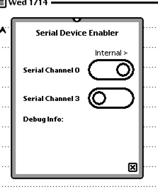
Eckhart’s code is an awesome blueprint for calling arbitrary memory locations, so it was easy to modify it to call these two functions.  Putting it all together, I whipped up this little Newton application:

Still a little more work to do, but good enough for development and testing.

Incidentally, when called with the correct parameters, the assembly behind SerialPort3LineDriverConfig is virtually identical to Eckhart’s code.  The SerialPort0LineDriverConfig is very similar but uses as GPIO instead of DIO.
The SerPortSel Pins

The internal serial port of the Newton MessagePad 2×00 exposes the same ports as the external interconnect.  In order to prevent two devices (one internal, one external) from diving the port at the same time, there are “Serial Port Select Pins” for Serial Channel 0 and Serial Channel 3.

The “Internal Serial Slot Designer’s Guide states:

Pin 1 PortSelect:
This is the control signal to select between a  peripheral in the internal Serial SLot and the Newton Interconnect Port.  When the signal is low, the Newton Interconnect POrt may drive the Serail Port 3 Signals.  When the signal is high, the Internal Serial Slot Peripheral may drive the Serial Port 3 Signals.

Pin 8 gpSerPortSel
This signal controls the LTC 1323 line driver for Serial Port 0 that drives the 26 pin Newton Interconnect Port.  When Low, the Newton Interconnect Port can drive Serial Port 0.  When high, the internal Serial Device can drive serial port 0 on the 32 pin connector.

The signals are most critical for Serial0, which has the LTC1323 driver on the main board which will attempt to drive the signal lines unless Pin 8 is high.  For Serial3, there are few (if any) devices that ever connected to the external interconnect port and used Serial3, so the potential for conflict is less.  Even still a “good citizen” will still honor these signals.  A bus driver buffer that can tristate these signals when not selected by these logic signals should probably be used.
One interesting wrinkle is an observation by Matthias Melcher:

Serial Port 0 uses gpSerPortSel on pin 8. When gpSerPortSel switches high, the card must respond with a low on DCD (5).

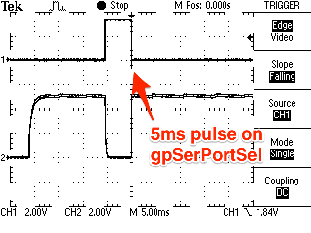
Basically, Matthias has found a sort of handshake where the Newton checks to see if a modem is present, and if the modem answers properly, it will leave the modem port selected.  I have not yet reproduced this, but I have seen a 5ms pulse when connecting to Serial0 on the Newton.  This pulse may be an interrogation.  I have yet try and respond on DCD to see if the port stays high (internal port selected).

The Internal Interconnect Port

I seem to have an odd, recurring interest in the internal serial port on the MP2x00.  A few years back I tried to make an internal bluetooth module.  It worked, but I never got the RF design correct so it didn’t work well.

Now, I’d like to try for an internal WiFi module.  I’m more hopeful that I can get the antenna correct by using more off the shelf components and, worst case, an external antenna.

The internal port was originally designed for an internal modem that was never produced.  Luckily, some of the design documents were leaked and are now available.  The documents give you part of the picture, but there are omissions and errors that make the process a bit more of an exercise in reverse engineering.

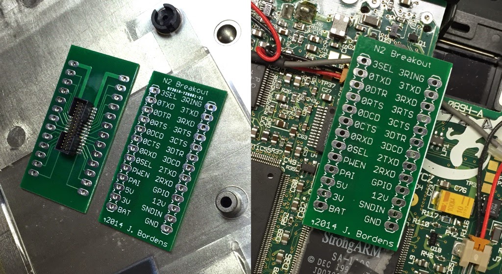
I wanted a breakout board that would help prototype and test the behavior of some of the GPIO pins and such.  I came up with this:

The connector is a FTE-116-01-G-DV-ES.  It is easier to find without the -ES option, FTE-116-01-G-DV-P for example is available from Newark electronics.  The ES is just an end shroud, which while a nice thing, is not strictly necessary.  I think the pins are a little longer than the original JAE connector, so it sits a little high.  The case seems to close so I’m hopeful that it’ll work for an internal card as well.

I had 20 of these boards made for $15.  You’ll have to solder the connector on there yourself, but if you’re playing around with this sort of thing, you probably know how to handle surface mount pins of this size.

Alternate UART for Sailfish

UART0, otherwise known as the Mightyboard’s primary serial port, is connected to the USB hardware and used for communicating with Replicator G. Both RevE and RevG Mightyboards have an unpopulated header that contains for the 2nd serial port, UART1. Normally unused on modern hardware, this second serial port was originally used for the RS485 chain for slave tools.

I wanted to use this UART1 for something useful, so I added some code to Sailfish that allows you to swap the primary UART0 traffic to UART1. This allows you to connect a serial device to UART1, such as a bluetooth serial module, or a network-to-TTL-serial adapter. Bluetooth serial modules should work pretty easily, but with a little coaxing, you can even get ReplicatorG to connect over the network.
Continue reading “Alternate UART for Sailfish”

Experimental Replacement for FlashAir Web User Interface

This is an experimental replacement for the FlashAir user interface. I use on my v2 card. I’m not if it’ll work with a v1 card, but it should.
This replacement UI for the FlashAir gives you a few more features on the web interface:

  1. Delete files from file list
  2. File upload progress
  3. Verify file size of upload to insure that it matches what’s on the FlashAir. (not a full diff like I do with the python script, due to javascript limitations)
  4. Drag and drop on browser window to upload.

Continue reading “Experimental Replacement for FlashAir Web User Interface”

$32 Network Print Server for Makerbot

Information on taking a LPC1768 and turning into a print server for the Makerbot. Use a Toshiba FlashAir to load your X3G file to the SD card, then use this to send the build command and start the print. The Mini-DK2 development board is $32 on eBay, or for $8 more you can have one with an LCD display. An mbed LPC1768 module from mbed.org works as well, but you’ll need a carrier board that has ethernet and a USB host port. This is built with the mbed.org toolchain, so you need to own at least one mbed module (LPC1768 of course) in order to access their online compiler and toolchain.
Continue reading “$32 Network Print Server for Makerbot”

Toshiba FlashAir WiFi-Enabled SD Card

SDCards.png

On the Makerbot Operator’s Group there was a discussion on network control of the Makerbot. A few options were discussed, including the EyeFi and the Toshiba FlashAir.

I decided to buy a FlashAir and see if I could get it to work. The ability to both download from and upload to the card is listed as a feature, and mentioned in many reviews. Unfortunately, there is no mention of the upload feature in the documentation or in the card’s UI.

Out of the box, the card broadcasts as a WiFi base station. When you connect to the card’s SSID, you then get a web server that allows you to read the files on the card. That’s about it. Settings are configured by a text file stored in a directory on the SD card.

Luckily, it seems like there is a trove of undocumented features on the card, including upload ability, and the ability to join an existing network. I posted to the Google Group with some information on how to use this card in a Makerbot. I’ve found a lot of information, so rather than multiple posts to the Google Group, I figured I’d post the info here.

Continue reading “Toshiba FlashAir WiFi-Enabled SD Card”